The Main Principles Of Wedge Barriers
Wiki Article
Wedge Barriers for Dummies
Table of ContentsEverything about Wedge BarriersWedge Barriers Fundamentals Explained
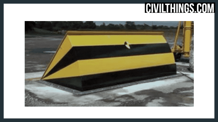
14 and the surface 12 to which the barrier 10 is secured might be made from concrete - Wedge Barriers. 2, the obstacle 10 is placed to or consists of an anchor or subframe (e. g., support 30 received FIG. 2 )protected underneath the surface 12. The bather 10 may be bolted to the support or safeguarded to the anchor by various other mechanical fasteners. In the illustrated embodiment, the obstacle 10 includes a wedge plate 16, which includes a portion that is considerably identical with the surface area 12 when the obstacle 10 remains in the withdrawed position. To put it simply, cars or individuals may overlook the obstacle 10 when the barrier 10 is in the pulled back setting and experience mild elevation family member to the surface area 12 while on the barrier 10. As discussed in information below, when the barrier 10 is in the released setting, the wedge plate 16 is held and sustained in an increased placement by a training mechanism of the barrier 10. In addition, the elements 18 may be bolted or otherwise mechanically coupled to one an additional. In this fashion, repair service or replacement of several components 18 might be streamlined and structured. That is, fixing or substitute of single components 18 may be done quicker, easily, and price properly. FIG. In specific embodiments, the anchor 30 may be a steel frame including plates, beam of lights(e. g., I-beams ), and/or other structures that are protected within the foundation 14, which may be concrete. At the surface 12, a top side 28 of the support 30 may go to least partly revealed , thus enabling the attachment of the barrier 10 to the anchor 30. g., threaded holes)in several light beams or plates of the anchor 30 may be revealed to the surface area 12. In this manner, screws 32 or other mechanical bolts might be used to secure the barrier 10 to the anchor 30. As the barrier 10 is placed to the surface area 12 of the foundation 14, collection of particles and other product underneath the barrier may be lowered, and parts of the bather 10 may not be revealed to listed below quality environments. As indicated by referral character 52, the lifting mechanism 50 consists of components disposed under the wedge plate 16. For example, the elements 52 beneath the wedge plate 16 may include an electromechanical actuator, a cam, one or even more cam surfaces, etc. Furthermore, the training system 50 includes a springtime setting up 54
The springtime rod 58 is coupled to a web cam(e. g., web cam 80 displayed in FIG. 4) of the lifting system 50. The springs 60 disposed about the springtime rod 58 are kept in compression by springtime sustains 62, including a fixed spring support 64. That is, the set springtime assistance 64 is repaired relative to the foundation 14 and the remainder of the bather 10.
8 Simple Techniques For Wedge Barriers
g., springtime support 65 )might be fixed to completion of the spring pole 58 to enable compression of the springtimes 60. As the springtimes 60 are pressed in between the spring sustains 62, the spring assembly 54 creates a force acting upon the web cam coupled to the spring rod 58 in an instructions 66. The staying pressure hop over to here used to the cam camera deploy release wedge plate 16 may be provided given an electromechanical actuator 84 or other various other. The spring assembly 54 and the actuator 84(e. g., electromechanical actuator)may run with each other to equate the webcam and lift the wedge plate 16.
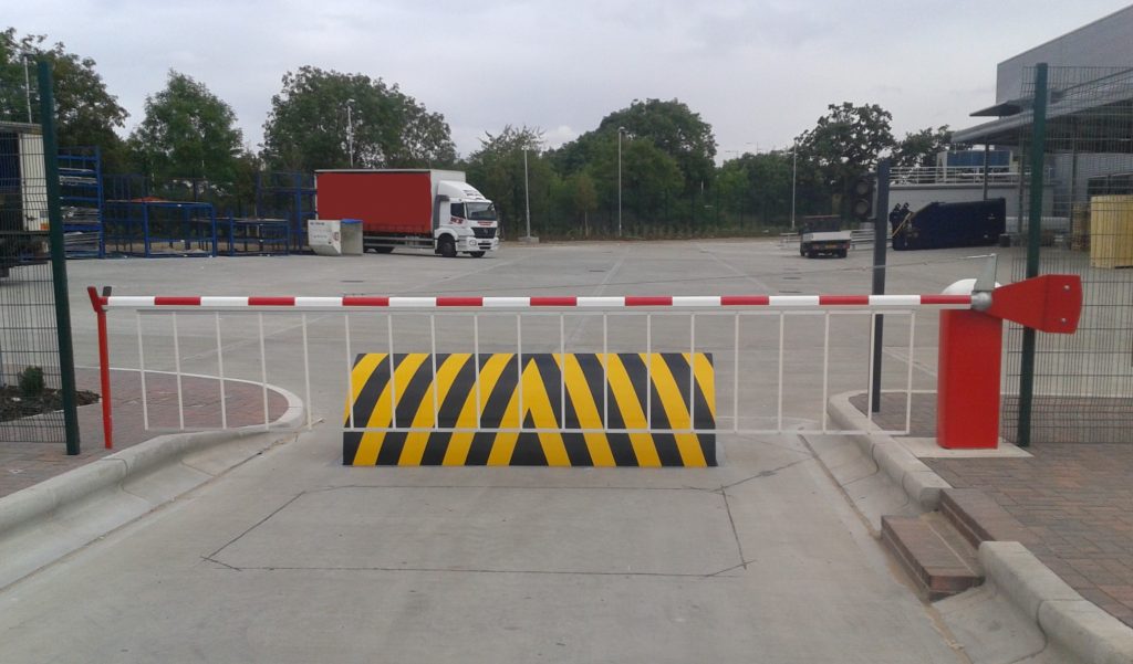
As stated above, the springtime setting up 54 exerts a constant force on the web cam, while the electromechanical actuator may be managed to apply a variable force on the web cam, therefore making it possible for the top article training and reducing( i. e., deploying and pulling back )of the wedge plate 16. In specific embodiments, the constant pressure used by the spring setting up 54 may be flexible. g., electromechanical actuator) is handicapped. As will be appreciated, the springtime setting up 54 may be covered and safeguarded from debris or other aspects by a cover plate(e. g., cover plate 68 shown in FIG. 4) that may be considerably flush with the raised surface 38 of the structure 14. As mentioned over, in the released position, the wedge plate 16 serves to obstruct access or traveling past the obstacle 10. As an example, the barrier 10(e. g., the wedge plate 16 )may obstruct pedestrians or lorries from accessing a residential property or path. As talked about above, the obstacle 10 is attached to the anchor 30 protected within the structure 14,
front brackets 71. Therefore, the link assemblies 72 might pivot and turn to make it possible for the collapse and expansion of the linkage settings up 72 throughout retraction and implementation of the bather 10. The linkage settings up 72 cause movement of the wedge plate 16 to be restricted. If a lorry is taking a trip towards the released wedge plate 16(e. For instance, in one scenario, the safety and security legs 86 might be extended throughoutmaintenance of the barrier 10. When the safety legs 86 are released, the safety and security legs 86 support the weight of the wedge plate 16 against the surface area 12. Consequently, the training system 50 may be shut down, serviced, gotten rid of, replaced, etc. FIG. 5 is partial perspective view of an embodiment of the surface-mounted wedge-style barrier 10, highlighting the web that site cam 80 and the cam surfaces 82 of the lifting system 50. Specifically, two webcam surfaces 82, which are described as lower cam surfaces 83, are positioned below the camera 80. The lower camera surfaces 83 might be fixed to the surface area 12 (e. As an example, the reduced cam surfaces 83 and the mounting plate 85 might create a solitary item that is protected to the support 30 by screws or various other mechanical fasteners. In addition, two web cam surface areas 82, which are referred to as upper cam surface areas 87, are placed over the cam 80 and combined to (e. In other personifications, intervening layers or plates might be placed between the surface area 12 and the reduced camera surfaces 83 and/or the wedge plate 16 and the upper cam surfaces 87 As mentioned over, the webcam 80 equates along the web cam surfaces 82 when the wedge plate 16 is lifted from the withdrawed placement to the released position. In addition, as mentioned above, the springtime setting up 54 (see FIG. 3 )might supply a force acting on the web cam 80 in the direction 102 by means of springtime pole 58, which might decrease the force the electromechanical actuator 84 is needed to use to the cam 80 in order to activate and raise the wedge plate 16. 1 )to the released placement(see FIG. 4). As revealed, the web cam 80 includes track wheels 104(e. g., rollers), which call and equate along the camera surface areas 82 during procedure.
Report this wiki page